


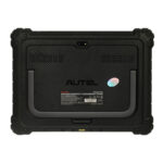
MaxiSYS Ultra
Original price was: 15.000,00 ر.س.14.507,00 ر.سCurrent price is: 14.507,00 ر.س. The price does not include Value Added Tax (VAT), which will be calculated during checkout.
The MaxiSYS Ultra car diagnostic and troubleshooting device from Autel is one of the best diagnostic and troubleshooting devices designed to maximize and make the most of technical andartificial intelligence technologies.
The MaxiSYS Ultra car diagnostic and troubleshooting device from Autel is one of the best diagnostic and troubleshooting devices designed to maximize and make the most of technical andartificial intelligence technologies.
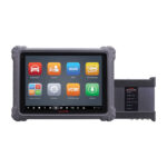
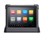
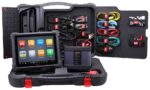
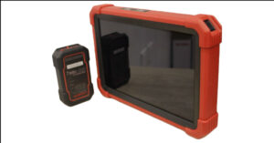
The MaxiSys Ultra is Autel’s most ambitious diagnostics tablet designed to maximize technician intelligence. It features a 12.9-inch touchscreen tablet with Android 7.0 OS powered by an Octa-core processor (2.3GHz Quad + 1.7GHz Quad), substantial 256GB built-in memory, all powering the new split-screen multi-application navigation to provide diagnostic guidance and test components to confirm repairs. Combined with the dynamic topology module mapping, enhanced AutoSCAN features and Intelligent Diagnostics options, the Ultra offers the technicians step-by-step repair guidance. The new MaxiFlash VCMI functions as a 4-channel oscilloscope, waveform generator, multimeter, and CAN BUS tester. The convenient docking station featured ensures you always have the power to scan.
MaxiSYS Ultra Description:

• Autel updates provide latest OE level coverage for more than 80 US Domestic, Asian and European vehicles, including supercar
• Exceptional OE-Level functionality from comprehensive OBDII diagnostics & services to advanced ECU coding and programming
• Automatic system and software updates with real-time push message notifications via internet
• Interactive Data Logging sessions enable direct contact with Autel Support for first-hand troubleshooting of diagnostic bugs and errors
• One-stop multitasking designed for ideal management of workshop operations to keep all data files, customer info, and vehicle records well organized
• Cloud-based Data Manager saves customer and vehicle records, scanner data and technician notes
MaxiSYS Ultra Specifications:

Operating System : Android 7.0.
Processor : 4GB RAM & 256GB On-board Memory.
Display : 12.9 inch TFT-LCD with 2732 x 2048 resolution & capacitive touch screen.
Connectivity :
- WiFix2 (802.11 a/b/g/n/ac 2×2 MIMO).
- BT v.2.1 + EDR.
- GPS.
- USB 2.0 (Two USB HOST Type A, one USB mini device).
- HDMI 2.0.
- SD Card (Support up to 256GB).
Camera : Rear: 16 Megapixel, Autofocus with Flashlight Front: 5 Megapixel.
Sensors : Gravity Accelerometer, Ambient Light Sensor (ALS).
Audio Input/Output : Microphone Dual Speakers 3-Band 3.5 mm stereo/standard headset jack.
Power and Battery :
18000mAh 3.8 V lithium-polymer battery
Charging via 12 V AC/DC power supply with the temperature between 0°C and 45°C
Input Voltage : 12V/3A Adapter.
Operating Temp. 0 to 50°C (32 to 122°F).
Storage Temperature : -20 to 60°C (-4 to 140°F).
Dimensions (WxHxD) : 366.5 mm (14.43″) x 280.9 mm (11.06″) x 34 mm (1.34″).
Protocols : DoIP, PLC J2497, ISO-15765, SAE-J1939, ISO-14229 UDS, SAE-J2411 Single Wire Can (GMLAN), ISO-11898-2, ISO-11898-3, SAE-J2819 (TP20), TP16, ISO-9141, ISO-14230, SAE-J2610 (Chrysler SCI), UART Echo Byte, SAE-J2809 (Honda Diag-H), SAE-J2740 (GM ALDL), SAE-J1567 (CCD BUS), Ford UBP, Nissan DDL UART with Clock, BMW DS2, BMW DS1, SAE J2819 (VAG KW81), KW82, SAE J1708, SAE-J1850 PWM (Ford SCP), SAE-J1850 VPW (GM Class2) .
MaxiSYS Ultra Accessories:


MaxiSYS Ultra Functional Description
1. 12.9″ TFT-LCD Capacitive Touch Screen
2. Ambient Light Sensor – detects ambient brightness
3. Power LED – refer to Table 2-1 Power LED Description for details
4. Front Camera
5. Built-in Microphone
MaxiSYS Ultra LED Color Description
Power : Green
Lights green when the Tablet is charging and the battery level is above 90%.
Lights green when the Tablet is powered on and the battery level is above 15%
Yellow Lights yellow when the Tablet is charging and the battery level is below 90%.
Power : Red
Lights red when the Tablet is powered on and the battery level is below 15%.

6. Docking Station Port
7. Collapsible Stand – extends from the back to allow hands-free viewing of the tablet
8. Speaker
9. Rear Camera
10. Camera Flash

11. Mini USB Port – Cannot be used with the USB Port simultaneously.
12. USB Port
13. USB Port
14. Mini SD Card Slot
15. HDMI (High-Definition Multimedia Interface) Port
16. Head Phone Jack
17. DC Power Supply Input Port
18. Lock/Power Button – long press to turn on and off the Tablet, or short press to lock the screen.

MaxiSYS Ultra Docking Station
- DC Power Port – connects to the AC/DC adapter for power supply.
- Charging Dock – holds the MaxiSys tablet for optimum viewing and convenient charging.
- Status Indicator Light.
The Indicator Light displays differently in response to the tablet status described below:
A. Green light – battery power of the tablet is sufficient (≥90%).
B. Yellow light – battery level is above 14% but below 90%.
C. Red light – battery level is below 14%.
NOTE : Ensure the charging dock is clear of any small metal or other conductive parts to avoid short circuit damage to the charger and the tablet.
MaxiSYS Ultra Power Sources
The tablet can receive power from any of the following sources:
- Internal Battery Pack.
- AC/DC Power Supply.
- Vehicle Power.
IMPORTANT Do not charge the battery when the temperature is lower than 0°C (32°F) or higher than 45°C (113°F).
MaxiSYS Ultra Internal Battery Pack
The tablet can be powered with the internal rechargeable battery, which if fully charged
can provide sufficient power for about 8 hours of continuous operation.
AC/DC Power Supply – using power adapter or docking station
The tablet can be powered from an electrical outlet using the AC/DC power adapter or
the docking station. The AC/DC power supply also charges the internal battery pack.
Vehicle Power
The tablet can be powered from the cigarette lighter or other DC power port on the test
vehicle through a direct cable connection. The vehicle power cable connects to the DC
power supply port on the top side of the display unit.
MaxiSYS Ultra Technical Specifications

Tablet Specifications
| Item | Description |
| Operating System | Android 7.0 |
| Processor | Samsung Exynos8895V octa-core Processor (2.3GHz Quad-core Mongoose + 1.7GHz Quad-core A53) |
| Memory | 4GB RAM & 256GB On-board Memory |
| Display | 12.9 inch TFT-LCD with 2732 x 2048 resolution & capacitive touch screen |
| Connectivity | WiFix2 (802.11 a/b/g/n/ac 2×2 MIMO) BT v.2.1 + EDR GPS USB 2.0 (Two USB HOST Type A, one USB mini device) HDMI 2.0 SD Card (Support up to 256GB) |
| Camera | Rear: 16 Megapixel, Autofocus with Flashlight Front: 5 Megapixel |
| Sensors | Gravity Accelerometer, Ambient Light Sensor (ALS) |
| Audio | Input / Output Microphone Dual Speakers 3-Band 3.5 mm stereo/standard headset jack |
| Power and Battery | 18000mAh 3.8 V lithium-polymer battery Charging via 12 V AC/DC power supply with the temperature between 0°C and 45°C |
| Input Voltage | 12V/3A Adapter |
| Operating Temp. | 0 to 50°C (32 to 122°F) |
| Storage Temp. | -20 to 60°C (-4 to 140°F |
| Dimensions (WxHxD) | 366.5 mm (14.43″) x 280.9 mm (11.06″) x 34 mm (1.34″) |
| Weight | 2.18kg (4.81 lb.) |
| Protocols | DoIP, PLC J2497, ISO-15765, SAE-J1939, ISO14229 UDS, SAE-J2411 Single Wire Can (GMLAN), ISO-11898-2, ISO-11898-3, SAE-J2819 (TP20), TP16, ISO-9141, ISO-14230, SAE-J2610 (Chrysler SCI), UART Echo Byte, SAE-J2809 (Honda Diag-H), SAE-J2740 (GM ALDL), SAE-J1567 (CCD BUS), Ford UBP, Nissan DDL UART with Clock, BMW DS2, BMW DS1, SAE J2819 (VAG KW81), KW82, SAE J1708, SAE-J1850 PWM (Ford SCP), SAE-J1850 VPW (GM Class2) |
MaxiSYS Ultra Docking Station Specifications
| Item | Description |
| Input Voltage | DC/12V/3A |
| Operating Temperature | 0°C to +45°C (ambient) |
| Storage Temperature | -20°C to +60°C (ambient) |
| Dimensions | (L x W x H) 396 x 136 x 54 (mm) |
| Weight | 0.98kg (2.1605lb.) |
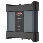
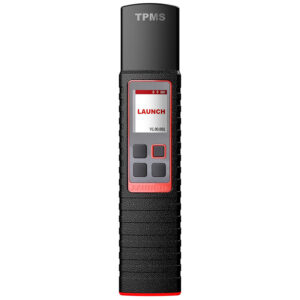
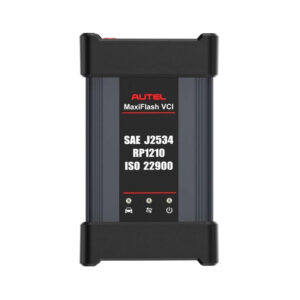
MaxiSYS Ultra MaxiFlash VCMI – Vehicle Communication and Measurement Interface
Functional Description

Multimeter Jacks
2. USB Port
3. Hook
4. DC Power Supply Input Port
5. Power Button
 6.Power LED – refer to Table 2-4 Power LED Description for details.
7. Battery LED – refer to Table 2-5 Battery LED Description for details.
8. Waveform generator LED – lights green when operating in the waveform generator mode.
9. Multimeter LED – lights green when operating in the multimeter mode.
10. Oscilloscope LED – flashes green when operating in the oscilloscope mode.
11. Vehicle LED – refer to Table 2-6 Vehicle LED Description for details.
IMPORTANT Do not disconnect the programming device while the vehicle LED status light is on! If the flash programming procedure is interrupted while the vehicle’s ECU is blank or only partially programmed, the module may be unrecoverable.

2. Ethernet Port
13. Vehicle Data Connector (DB26-Pin)
14. Input Channel A
15. Input Channel B
16. Input Channel C
17. Input Channel D
MaxiSYS Ultra Power LED Description
Power
Yellow Lights yellow automatically at power up when VCMI is selftesting.
Green Lights solid green when powered on.
Red
1. Lights solid red when system failure occurs.
2. Flashes red when VCMI is upgrading.
MaxiSYS Ultra Battery LED Description
Battery Green
1. Flashes green when VCMI is charging.
2. Lights solid green when fully charged or the battery level is above 50%.
Yellow Lights yellow when the battery level is above 25% but below 50%.
Red
1. Lights red when the battery level is above 10% but below 25%.
2. Flashes red when the battery level is below 10%
MaxiSYS Ultra Vehicle LED Description
Vehicle
Green
- Lights solid green when connected via USB cable.
- Flashes green when communicating.
Blue
Lights solid blue when connected via BT. Flashes blue when communicating.
Cyan
(Blue/Green)
Lights solid cyan when connected via Wi-Fi. Flashes cyan
(blue/green) when communicating.
Magenta
(Blue/Red)
Lights solid magenta when connected via Internet cable.
Flashes magenta (blue/red) when communicating.
NOTE
Sometimes the vehicle LED lights yellow when the VCMI device is connected by other tablets, please wait for 2 minutes to automatically
disconnect them, or when the Wi-Fi signal is weak, please try to reconnect the VCMI.
MaxiSYS Ultra Communication Capability
The Vehicle Communication and Measurement Interface supports Bluetooth (BT), Wi-Fi and USB communications. It can transmit vehicle data to the tablet with or without a cable connection.
In open areas, the working range of the transmitter through BT communication is up to 328 feet (100 m). The working range of 5G Wi-Fi is up to 164 feet (50 m). If the signal is lost due to being taken out of range, communication will be restored
once the tablet is within range.
MaxiSYS Ultra Measurement Capability
The VCMI device is designed with the functions of multimeter, oscilloscope, waveform generator and OBDII CAN Bus Check. The parameters such as voltage, resistance, current, signal frequency, and voltage-time characteristic of the signal can be measured and the results are displayed on the tablet.
MaxiSYS Ultra Programming Capability
The VCMI device is a D-PDU, SAE J2534 & RP1210 compliant PassThru programming interface device. Using the updated OEM software, it is capable of replacing the existing software/firmware in the Electronic Control Units (ECU), programming new ECUs and fixing software-controlled drivability issues and emission issues.
MaxiSYS Ultra Power Sources
The VCMI device can receive power from the following sources:
1. Vehicle Power
2. AC/DC Power Supply
3. Built-in rechargeable Battery Pack
Vehicle Power
The VCMI device operates on 12/24 Volt vehicle power, which receives power via the
vehicle data connection port. The device powers on whenever it is connected to an OBD
II/EOBD compliant data link connector (DLC). For non OBD II/EOBD compliant vehicles,
the device can be powered from a cigarette lighter or other suitable power port on the
test vehicle using the auxiliary power cable.
AC/DC Power Supply
The VCMI device can be powered from a wall socket using the AC/DC power adapter. Built-in Battery Pack
The VCMI device can also be powered with its built-in 3750mAh battery pack.
MaxiSYS Ultra Accessories Kit
Main Cable
The VCMI device can be powered through the Autel Main Cable V2.0 (the V2.0 icon can be seen on the cable) when connected to an OBD II/EOBD compliant vehicle.
The Main Cable connects the VCMI device to the vehicle’s data link connector (DLC), through which the VCMI device can transmit vehicle data to the tablet.
OBD I-Type Adapters
The OBD I-type adapters are for Non-OBDII vehicles. The adapter used depends on the type of vehicle being tested. The most common adapters are shown below (Adapters may be sold separately, please contact your distributor for details).

MaxiSYS Ultra Other Accessories


MaxiSYS Ultra Getting Started
Make sure the tablet has sufficient power or is connected to the external power supply.
MaxiSYS Ultra Power Up
Long press (press and hold) the Lock/Power button on the top right side of the tablet to switch the unit on. The system boots up and shows the lock screen with 3 entry options:
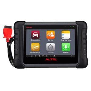
1. MaxiSys Home – Swipes up the MaxiSys Home icon to enter the MaxiSys Job Menu shown as below.
2. Unlock – Swipes up the Lock icon at the center to unlock the screen or enter the MaxiSys Job Menu when booting up.
3. Camera – Swipes up the Camera icon to launch the camera.

1. Application Buttons
2. Locator and Navigation Buttons
3. Status Icons
NOTE
It is recommended to lock the screen when not in use to protect information in the system and conserve the power.
Almost all operations on the tablet are controlled through the touchscreen. The touchscreen navigation is menu driven allowing for quick access you to test procedure, or data that you need, through a series of questions and options. Detailed descriptions of the menu structures are found in the chapters for each application.
MaxiSYS Ultra Application Buttons
The table below briefly describes each of the applications in the MaxiSys system.
Applications
| Diagnostics |  |
Accesses the unit’s diagnostics functions. |
| Service |  |
Accesses special functions menu. |
| Measurement |  |
Software tools that measure vehicle system parameters such as voltage, resistance, current, and monitor signal activities. |
| Data Manager |  |
Accesses the saved repair shop, customer and vehicle data including detail vehicle diagnostics and test record history |
| Settings |  |
Accesses the system settings menu and general tablet menu. |
| Update |  |
Accesses system software update menu. |
| VCMIManager |  |
Accesses VCMI connection menu |
| ADAS |  |
Accesses ADAS systems menu. |
| Support |  |
Synchronizes Autel’s online service database with the MaxiSys tablet. |
| Remote Desktop |  |
Configures your unit to receive remote support using the TeamViewer application. |
| Quick Link |  |
Provides associated website bookmarks to allow quick access to product update, service, support and other information. |
| MaxiViewer |  |
Provides a quick search for supported functions and/or vehicles. |
| MaxiVideo |  |
Configures the unit to operate as a video scope device by connecting to an Imager head cable for close vehicle inspections. |
MaxiSYS Ultra Locator and Navigation Buttons
Operations of the Navigation buttons at the bottom of the screen are described in the table below:
| Locator |  |
Indicates the location of the screen. Swipe the screen left or right to view the previous or next screen. |
| Back |  |
Back Returns to the previous screen. |
| Android Home |  |
Returns to Android System’s Home screen. |
| Recent Apps |  |
Displays a list of applications that are currently running. Tap an app icon to launch. Remove an app by swiping it to the right. |
| Split Screen |  |
Tap icon to display a split screen. |
| Browser |  |
Launches the Chrome Internet browser. |
| Camera |  |
Tap icon to open camera viewfinder. Press and hold icon to capture screenshot of display screen. The saved files are auto-stored in the Data Manager application for later review |
| Display & Sound |  |
Adjusts the brightness of the screen and the volume of the audio output. |
| MaxiSys Home |  |
Returns to MaxiSys Job Menu. |
| VCMI |  |
Opens the VCMI Manager application. A green icon at the bottom right corner indicates the VCMI device is connected, a red X icon will display if connection fails. The battery status icon displays the remaining VCMI power. |
| MaxiSysShortcut |  |
Returns to the Diagnostics screen. |
| Service |  |
Returns to the Service screen. |
MaxiSYS Ultra To use the camera
1. Tap the Camera button. The camera screen opens.
2. Focus the image to be captured in the view finder.
3. Tap the camera icon on the right side of the screen. The view finder now shows
the captured picture and auto-saves the taken photo.
4. Tap the thumbnail image on the top right corner of the screen to view the stored image.
5. Tap the Back or Home button to exit the camera application.
NOTE
After swiping the camera screen from left to right, the camera mode and video mode can be switched by tapping the blue camera icon or video icon.
Refer to Android documentation for additional information.
MaxiSYS Ultra System Status Icons
Your MaxiSys tablet is a fully functional Android tablet with the standard Android operation system status icons. Refer to Android documentation for additional information.
MaxiSYS Ultra Power Down
All vehicle communications should be terminated before shutting down the tablet. A warning message displays if a shutdown is attempted while the tablet is communicating with the vehicle. Forcing a shut down while the tablet is communicating with the vehicle 19 may lead to ECU problems on some vehicles. Please exit the Diagnostics application
before shutting off the tablet.
To power down the MaxiSys tablet:
1. Long press (press and hold) the Lock/Power Button.
2. Tap Power off option.
3. Tap OK.
3.2.1 Reboot System
In case of system crash, long press the Lock/Power button and tap Reboot to restart the system.
MaxiSYS Ultra Diagnostics

The Diagnostics application can access the electronic control module of multiple vehicle control systems, including but not limited to
the engine, transmission, antilock brake system (ABS) and airbag system (SRS).
Establish Vehicle Communication and Selection
Establish Vehicle Communication
The Diagnostics operations require connecting the MaxiSys Ultra Diagnostic tablet to the test vehicle through the VCMI device using the Main Cable.
(Use the applicable OBD Itype adapter if needed).
To establish proper vehicle communication to the tablet, you need to perform the following steps:
1. Connect the VCMI device to the vehicle’s DLC for both communication and power source.
2. Connect the VCMI device to the tablet via BT pairing, Wi-Fi or USB connection.
3. When the above steps are completed, check the VCMI navigation button at the
bottom bar on the screen, if a green BT, Wi-Fi or USB icon displays at the lower right corner, the MaxiSys Ultra Diagnostic Platform is ready to start vehicle diagnosis.
MaxiSYS Ultra Vehicle Connection
The method used to connect the VCMI device to a vehicle’s DLC depends on the vehicle’s configuration as follows:
- A vehicle equipped with an On-board Diagnostics Two (OBD II) management system supplies both communication and 12-volt power through a standardized J-1962 DLC.
- A vehicle not equipped with an OBD II management system supplies communication
through a DLC connection, and in some cases supplies 12-volt power through the cigarette lighter receptacle or a connection to the vehicle battery.
MaxiSYS Ultra OBD II Vehicle Connection
This type of connection only requires the main cable without any additional adapter.
MaxiSYS Ultra To connect to an OBD II vehicle
1. Connect the main cable’s female adapter to the Vehicle Data Connector on the VCMI device, and tighten the captive screws.
2. Connect the cable’s 16-pin male adapter to the vehicle’s DLC, which is generally located under the vehicle dash.
NOTE
The vehicle’s DLC is not always located under the dash; refer to the user manual of the test vehicle for additional connection information.
MaxiSYS Ultra Non-OBD II Vehicle Connection
This type of connection requires both the main cable and a required OBD I adapter for the specific vehicle being serviced.
There are three possible conditions for Non-OBD II vehicle connection:
- DLC connection supplies both communication and power.
- DLC connection supplies communication and power is to be supplied via the cigarette lighter connection.
- DLC connection supplies communication and power is to be supplied via connection to the vehicle battery.
MaxiSYS Ultra To connect to a Non-OBD II Vehicle
1. Connect the main cable’s female adapter to the Vehicle Data Connector on the VCMI device, and tighten the captive screws.
2. Locate the required OBD I adapter and connect its 16-pin jack to the main cable’s male adapter.
3. Connect the attached OBD I adapter to the vehicle’s DLC.
NOTE
Some vehicles may have more than one adapter or may have test leads instead of an adapter.
Make the proper connection to the vehicle’s DLC as required.
To connect the cigarette lighter
1. Plug the DC power connector of the cigarette lighter into the DC power supply input port on the device.
2. Connect the male connector of the cigarette lighter into the vehicle’s cigarette lighter receptacle.
To connect the clipper cable
1. Connect the tubular plug of the clipper cable to the male connector of the cigarette lighter.
2. Plug the DC power connector of the cigarette lighter into the DC power supply input port of the VCMI device.
3. Connect the clipper cable to the vehicle’s battery.
To download the user guide click here
Only logged in customers who have purchased this product may leave a review.
Related products

MaxiCheck MX808
1.690,00 ر.س The price does not include Value Added Tax (VAT), which will be calculated during checkout.

MaxiPRO MP808TS Car diagnostic devices
3.600,00 ر.س The price does not include Value Added Tax (VAT), which will be calculated during checkout.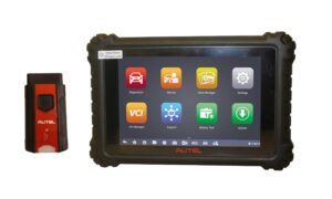
MaxiSYS MS906 Pro
5.126,09 ر.س The price does not include Value Added Tax (VAT), which will be calculated during checkout.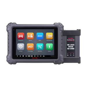
MaxiSYS MS909 Autel Diagnostic Scanner
9.400,00 ر.س The price does not include Value Added Tax (VAT), which will be calculated during checkout.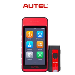
MaxiTPMS ITS600
1.900,00 ر.س The price does not include Value Added Tax (VAT), which will be calculated during checkout.

Autel MaxiBAS BT506 In and Out vehicle Battery Tester
Original price was: 210,00 ر.س.148,00 ر.سCurrent price is: 148,00 ر.س. The price does not include Value Added Tax (VAT), which will be calculated during checkout.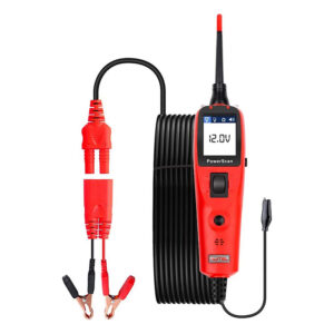
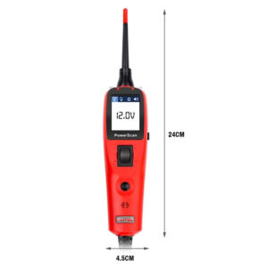
Powerscan PS100
Original price was: 440,00 ر.س.420,00 ر.سCurrent price is: 420,00 ر.س. The price does not include Value Added Tax (VAT), which will be calculated during checkout.
Reviews
There are no reviews yet.